Mass-Manufacturing Synthetic Hagfish Skeins
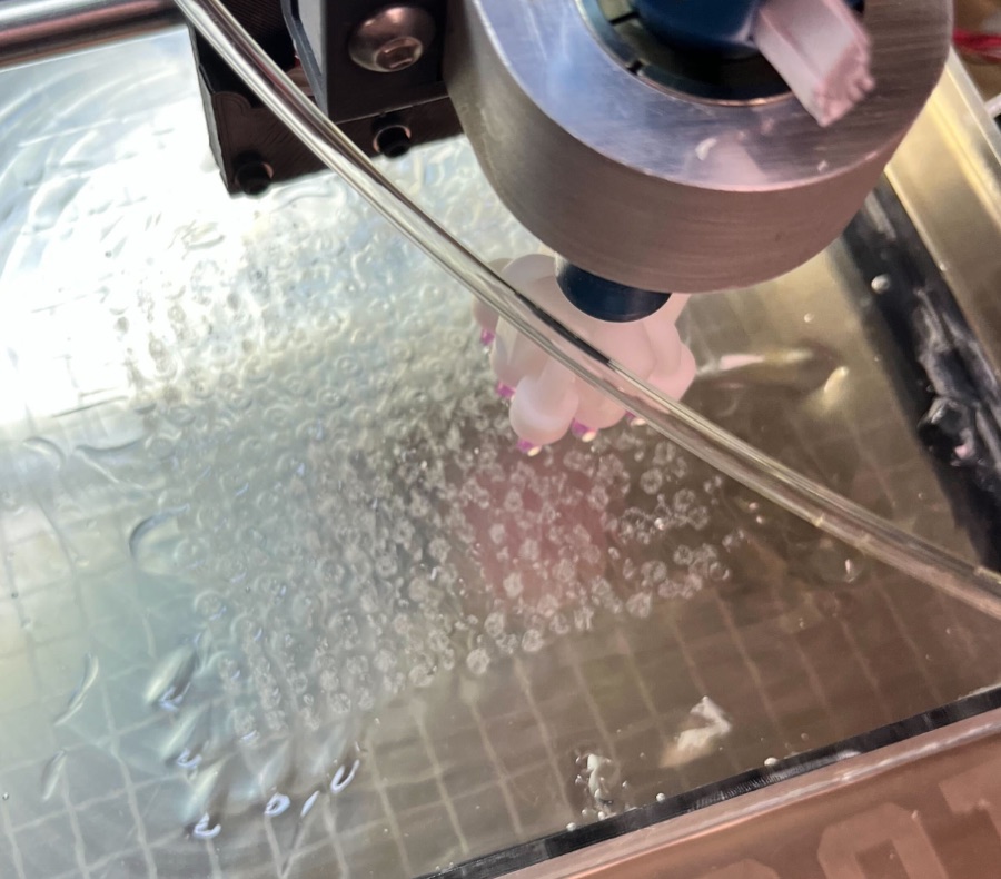
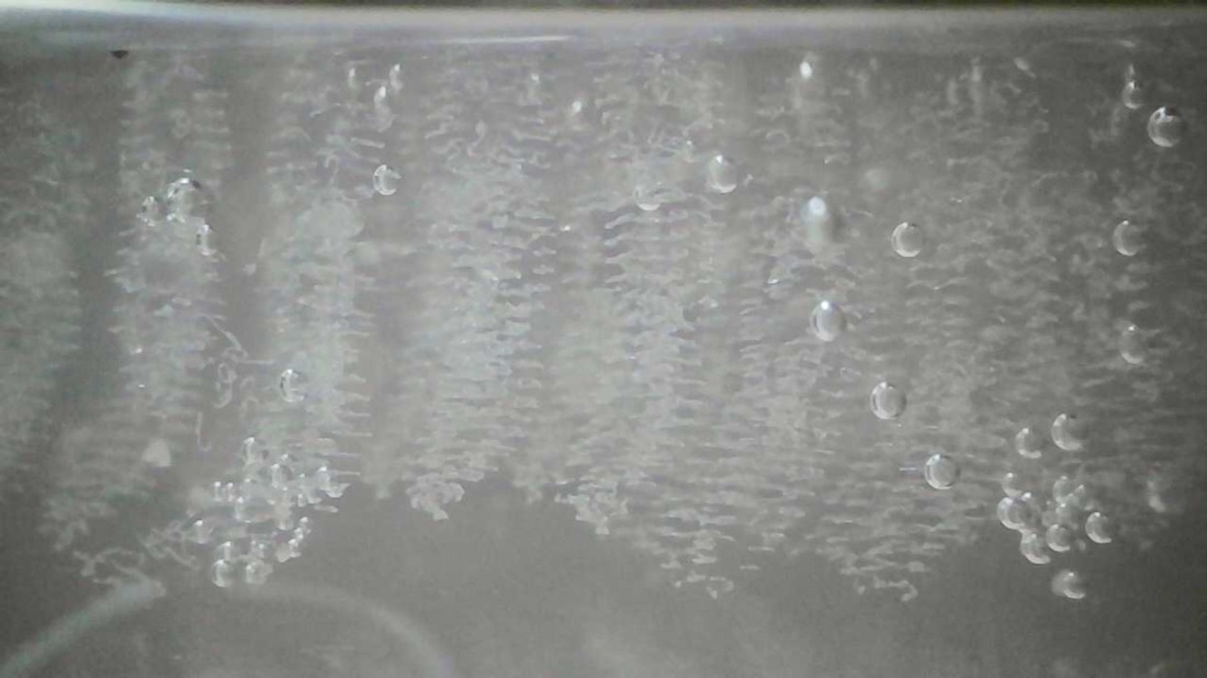
Hagfish defend themselves with slime. Packed inside it are skeins: microscopic bundles of thread, coiled tight, that unravel the instant they hit flowing water and expand into a huge net. In the Kinetic Materials Research Group at UIUC, we printed synthetic skeins by drawing a polymer thread through a gel. As principal researcher, I led the work on the group's DARPA deliverable: scaling that process from one skein at a time to mass manufacturing.
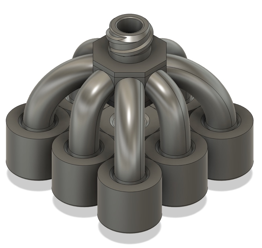
manifold
single print
against an 8 h target
The problem
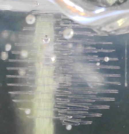
We print each skein by extruding 25 wt% SEBS (a rubbery polymer dissolved in toluene) through a fine needle into Carbopol gel. The gel acts as a scaffold, holding every loop of thread exactly where the needle left it. One skein packs most of a metre of thread into a bundle less than a centimetre tall.
DARPA's target was 1 km of thread, about 1,000 skeins, in under 8 hours. At roughly 3 minutes per skein, a single nozzle would need 50 hours. That left two levers: print many skeins at once, and stop wasting time between prints.
Approach 1: many nozzles at once
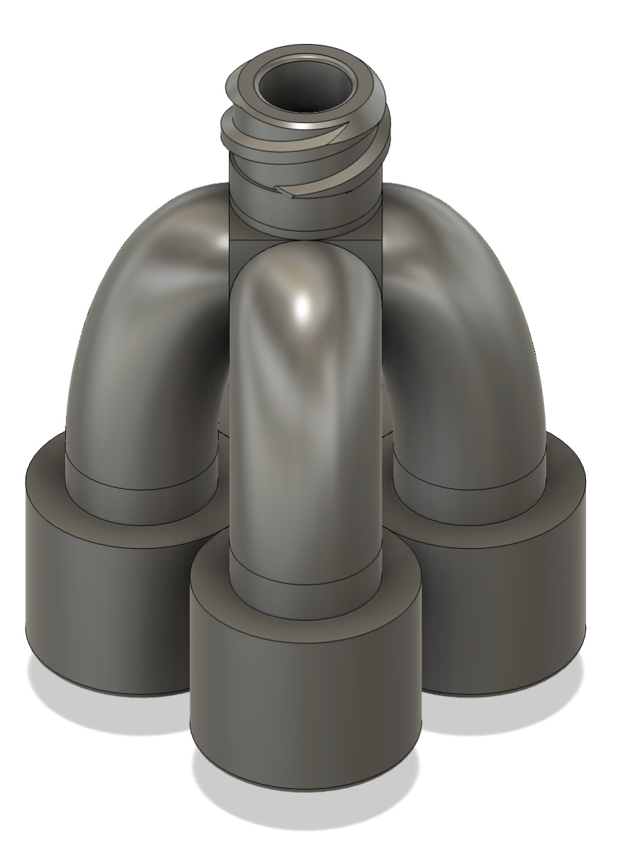
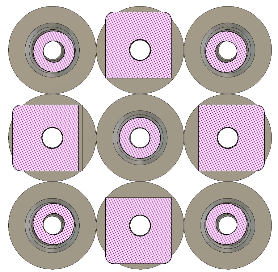
I replaced the single glass micro-needle with metal 34-gauge needles fed by a 3D-printed manifold: one pressurized syringe in, several needles out. A 4-nozzle version let us run cheap tests; the 9-nozzle version was the real target.
| Setup | Print runs needed | Time for 1,000 skeins |
|---|---|---|
| Single nozzle | ~1,000 | 50 h |
| 4-nozzle manifold | ~250 | 12.5 h |
| 9-nozzle manifold | ~112 | 5.5 h |
Keeping it from leaking
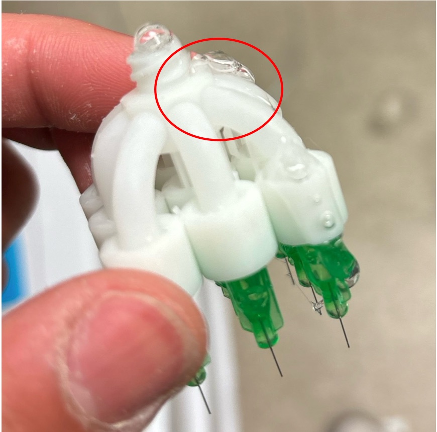
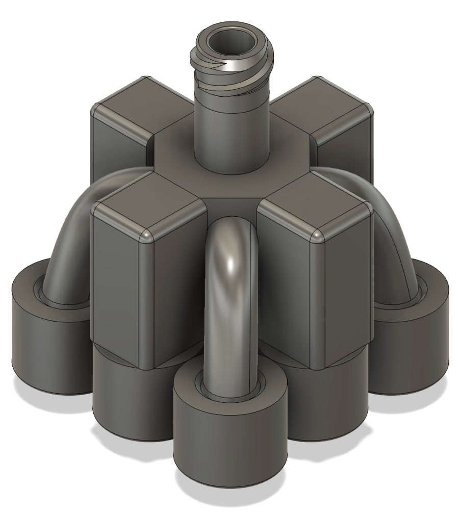
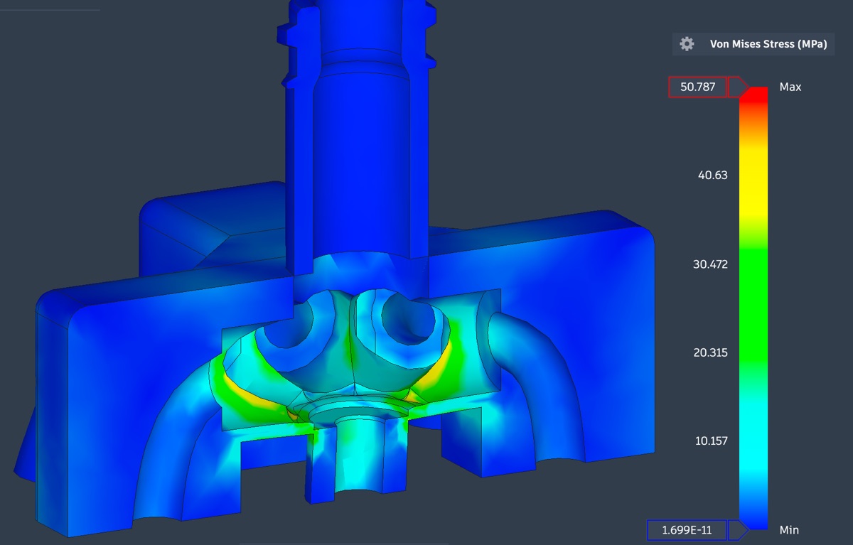
The first manifold held pressure fine in testing, then started leaking after about five hours of use. The leaks were all at the thinnest walls: high stress concentration there was causing fatigue failure. I thickened those walls and switched resins from Clear V4 to the stiffer Rigid 4000, which raised stiffness by about 45% and cut deformation at the failure point by about 30%, so the seals stay tight.
FEA puts the peak von Mises stress at \(\sigma_1 = 50.8\) MPa for every 1 MPa of internal pressure, so stress scales as \(\sigma = \sigma_1 P\). With Rigid 4000's \(S_{ut} = 69\) MPa, the static limits are:
$$P_{\text{burst}} = \frac{S_{ut}}{\sigma_1} \approx 1.36 \text{ MPa}, \qquad P_{\text{allow}} = \frac{P_{\text{burst}}}{3} \approx 0.45 \text{ MPa}$$But the real failure was fatigue. Pressure cycles from zero to \(P\), so the alternating and mean stresses are both \(\sigma_1 P / 2\). The Goodman criterion with a safety factor \(n\) is
$$\frac{\sigma_a}{S_e} + \frac{\sigma_m}{S_{ut}} = \frac{1}{n}$$Taking the conservative polymer assumption \(S_e = 0.25\,S_{ut}\) and solving for pressure:
$$P_{\text{fatigue}} = \frac{0.4\, S_{ut}}{\sigma_1\, n} = \frac{0.4 \times 69}{50.8 \times 1.5} \approx 0.36 \text{ MPa}$$That 360 kPa became the manifold's maximum working pressure, about four times the 75–85 kPa we actually print at.
Making the flow even
Two flow problems showed up. First, the nozzles didn't start together: outer needles sit further from the inlet, so thread appeared at different times. Second, it took a surprisingly high pressure to get any flow at all. Both came down to the same physics, viscous flow in narrow tubes, and some hand calculations showed exactly where the pressure was going.
For slow, viscous flow in a tube, the Hagen–Poiseuille law gives the pressure drop:
$$\Delta P = \frac{8 \mu L Q}{\pi r^4}$$With the ink's viscosity \(\mu \approx 1\) Pa·s and a flow of \(Q \approx 0.03\) µL/s per needle, a 34G needle (\(r = 54\) µm, \(L = 6.35\) mm) needs about 57 kPa. A manifold channel (\(r = 1.25\) mm, \(L = 12\) mm) needs about 0.4 Pa. Because of that \(r^4\), the needles take around \(10^5\) times more pressure than the manifold, so the manifold's shape barely matters for the pressure. 57 kPa matched what we measured, which made it a good starting point for testing.
The same result fixes the delay. Every branch sees essentially the same flow \(Q\), so the time to fill a branch of length \(L_i\) is
$$t_i = \frac{V_i}{Q} = \frac{\pi r_i^2 L_i}{Q} \quad\Rightarrow\quad r_i^2 L_i = \text{constant}$$For branches of 15, 12 and 8 mm, that gives channel diameters of 2.2, 2.5 and 3.1 mm. Longer paths get narrower channels and every nozzle starts at once. After this change, testing confirmed the delay was gone.
Dialing in the print
With the manifold working, we swept the pressure. At 55 kPa the threads came out thin and broke; at 65 kPa they were better but still broke. The sweet spot was 75–85 kPa at 5 mm/s: consistent fibres with little to no breakage. Any higher and the thread thickened into blobs.
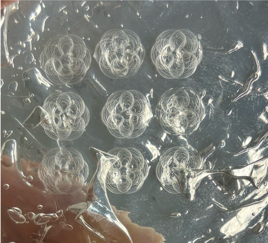
The first full 9-nozzle prints came out clean: nine separate skeins with plenty of space between them, no tangling, and no visible breaks in the thread.
Approach 2: packing a thousand skeins into one block
Swapping in a fresh gel container takes about 30 minutes, too slow to do many times within the 8-hour budget. So the whole run had to fit in one container, which meant packing skeins as tightly as possible without any two touching. A skein that touches another counts as ruined.
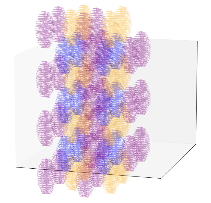
The answer came from crystallography. Arranging skeins like atoms in a face-centred cubic (FCC) lattice fills 74% of the space, against 68% for body-centred cubic. It takes six interleaved printing passes per cell instead of three, but the extra density was worth it.
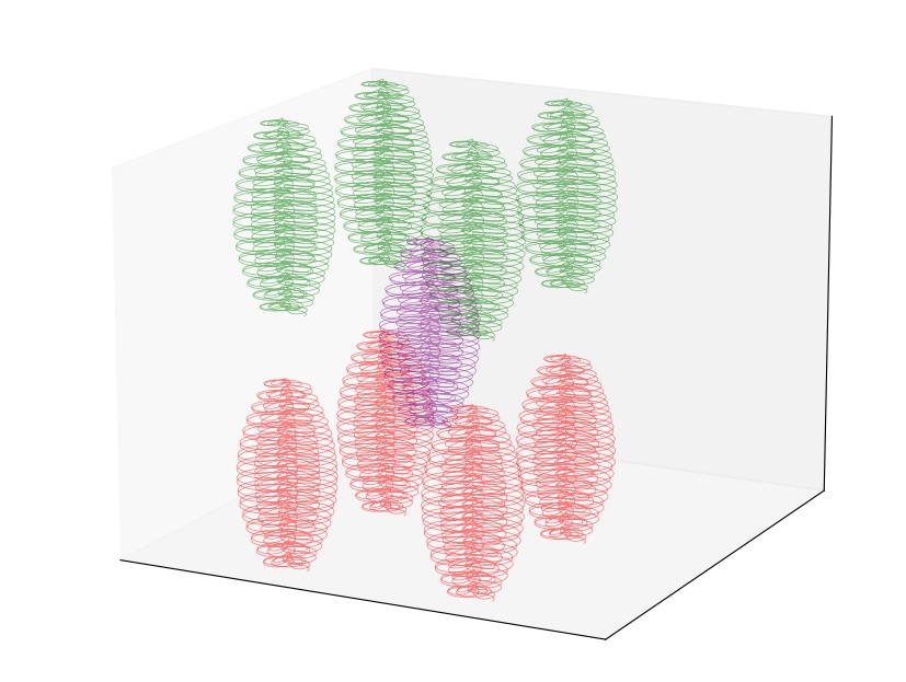
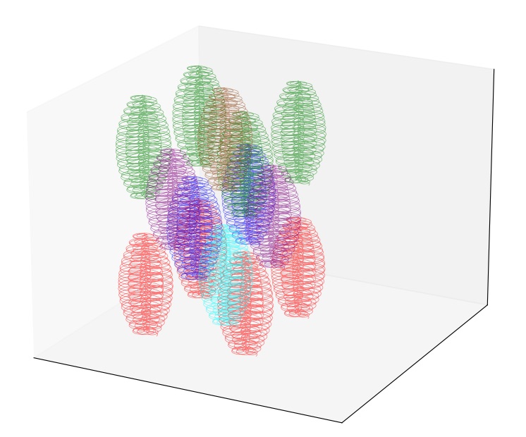
Interweaving brought new failure modes. The moving needle shears the gel and can drag skeins it has already printed, and in stiff gel the thread "bounces" and clumps around the nozzle. Tests across skein sizes showed both problems disappear for skeins no wider than 4 mm, printed in a softer 10 Pa gel. The trade-off is that soft gel makes the first loops harder to anchor. We settled on skeins 8 mm tall and 2.8 mm in radius, which keep the roughly 100× expansion ratio the design relied on.
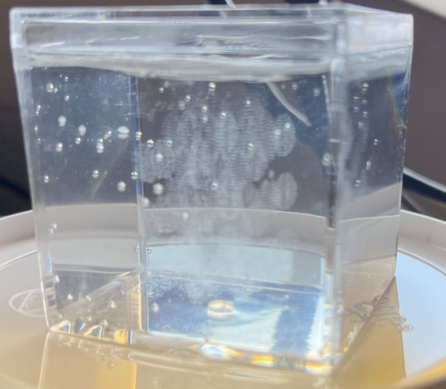
The first 3D interweaving test packed 56 skeins in 7 layers: 40.4 m of thread in 27 minutes, matching the simulated FCC layout.
Scaling up
The full-scale plan was 1,080 skeins in a true FCC arrangement, filling a block about 6.3 × 5.1 × 0.9 inches, with an estimated print time of 6 hours, comfortably inside the 8-hour target. The G-code path for the whole network was generated from the same skein model.
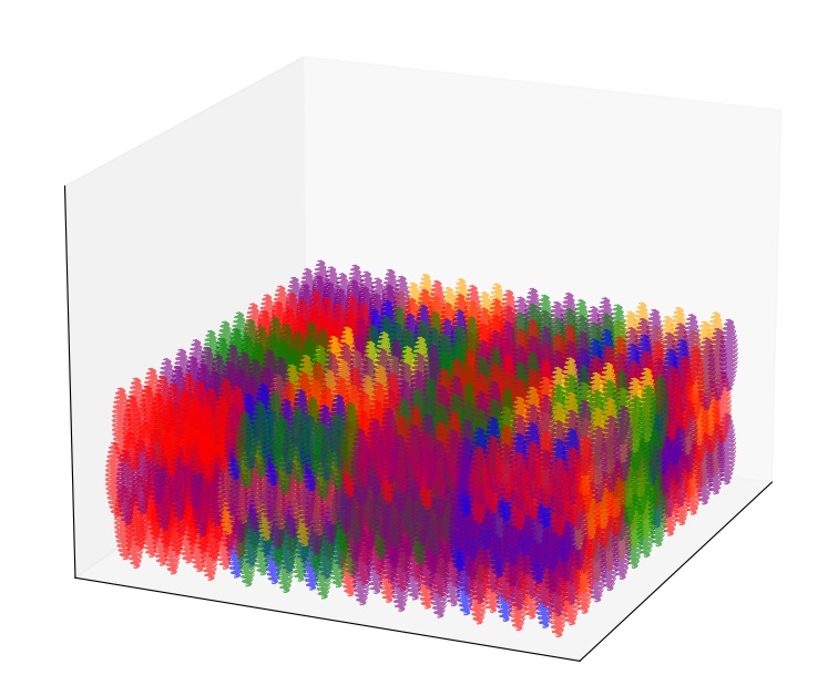
The long print ran on a modified off-the-shelf printer with the 9-nozzle manifold, 10 Pa gel and 34G needles. Soft gel was a must at this size: filling a container this large with 50 Pa gel trapped air pockets that would ruin a long print. There were occasional breaks in the thread, but DARPA judged the yield a success, and the run demonstrated that skeins can be mass-manufactured. The next step we recommended was tuning skein geometry and print settings under full production conditions to cut those breakages.